
Flexible and Secure Field Bus Networks
PROFIBUS - BITBUS - DIN-MESSBUS - SINEC L2 - MODBUS - ...
Index for this page:
- Introduction
- Limitations of Pure RS-485 Systems
- Problems of Netzwerk Management
- Use of Repeatern
- Properties of the DIA-LOG Repeater
- Suppression of Line Noise
- Integration into Existing Networks
- Use of Star Repeaters
- Properties of the DIA-LOG Star Repeater
- Why Use DIA-LOG Repeaters and Star Repeaters
- Line Parameters, Line Length und Transfer Rate
| Introduction | |
|---|---|
| In process automation and industrial communication, field busses build the basis on the lowest layers of automation technology. Todays technology cannot be thought without them anymore and they will gain even more significance with the increasing decentralization in automation. On of the most widespread interface norms is the EIA-Standard 1 RS-485, which describes the electrical properties of the field bus. | Importance of RS-485 |
| It offers good EMV properties (noise immunity, noise radiation) and cost effective implementation possibilities and is not expected to be replaced by other systems in the forseeable future. Its protocol independence makes a broad variety of applications possible. | EMC Properties |
| Tody several different field bus systems have been implemented and established upon the RS-485 interface norm, e.g. PROFIBUS, SINEC L2, BITBUS, DIN-MESSBUS, FIP, etc. | RS-485 Field Busses |
| Limitations of Pure RS-485 Systems | |
|---|---|
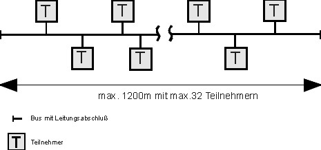
| An important part of an RS-485 interface are the driver or coupling components. They define the major part of the physical properties und limit the capabilities of an RS-485 field bus system. | Driver Component |
|
|
| The figure shows the simple network topology resulting from the physical limitations of the RS-485 norm. | |
|
| Problems in Network Management | |
|---|---|
|
This strict network topology cannot always be kept for modern
field bus systems. Network management is made difficult with pure RS-485 systems.
Because ... |
|
|
|
| Single segments of the network cannot be switched off for maintenance purposes, making service and extension of existing networks a particularly cost intensive task. |
DIA-LOG RS-485 Repeater
| Applications for Repeaters | |
|---|---|
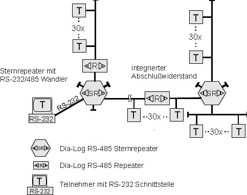
| In order to raise the number of possible participants as well as the maximum line length, repeaters are used in RS-485 field bus systems. They are basically integrated into the network as a passive participant, enabling 31 further participants to be connected. To achieve this, they build a new bus segment which again can have the maximum line length. That way a limited tree topology is possible. |
Bus Segments Tree Topology |
| Properties of the DIA-LOG Repeater | |
|---|---|
On top of the basic properties of a general repeater, the DIA-LOG RS-485
star topology repeater offers further advantages:
It is fully cascadable. |
|
|
| Suppression of Line Noise | |
|---|---|
Using integrated active and passive components, line noise occuring even in smaller networks are suppressed.
|
| Integration into Exitsting Networks | |
|---|---|
The DIA-LOG RS-485 repeater can be seamlessly integrated into existing networks.
No restructuring of the network is needed whatsoever.
|
DIA-LOG RS-485 Star Repeater
| Applications of Star Repeaters | |
|---|---|
| Star topology repeaters (couplers) are used to establish tree or star shaped networks respectively. Opposed to traditional repeaters they provide six rather than only two equal RS-485 interface ports. | Star Topology |
| Properties of the DIA-LOG Star Repeater | |
|---|---|
|
6xRS-485 optional RS-232 converter optional Echo cascadable |
|
Why Use DIA-LOG Repeaters and Star Repeaters |
|
|---|---|
|
Economic Efficiency DIA-LOG repeaters and DIA-LOG star topology repeaters can of course be uses together in the same network. Through the extended possbiilites for structuring the network and the integrated mechanisms for noise suppression the economic efficiency and flexibility of the network is significantly increased. |
Economic Efficiency |
|
Transfer Security The use of DIA-LOG repeaters does not only pay off when exceeding the maximum allowed number of participants (32) or line length (300-1200 m) for a field bus network. Through the built-in noise suppression mechanisms, the signal transfer quality can be improved or even only made possible for smaller or less branched networks. This is especially befenicial in critical sections (strong disturbances, networks close to the theoretical limits, potential differences between the participants). The integrated surge protection offers additional safety even under exceptional circumstances. |
Transfer Security |
|
Network Security In a pure line topology, any bus failures (e.g. mechanical bus line damage) have an immediate effect on the entire network. In tree or star topologies, bus failures are limited to the affected network segment only. |
Network Security |
|
Ease of Service Through the separation into single network segments, service and maintenance, e.g. at finding an error, extending the network or doing test runs, are made a lot easier. |
Ease of Service |
|
Wide Area Network Due to the full cascadability, the DIA-LOG repeater permits the creation of heavily branched networks with subnets of varying topology. Even distant buildings become interconnectable. In combination with an external lightning protection, aerial lines are supported. |
Wide Area Networks |
|
Advantages of DIA-LOG Repeaters and Star Repeaters
|
| Line Parameters, Line Length and Transfer Rate, Bus Termination | |||||||||||||||||||||||||
|---|---|---|---|---|---|---|---|---|---|---|---|---|---|---|---|---|---|---|---|---|---|---|---|---|---|
|
a) Line Parameters The bus line for the RS-485 data transmission is specified in EN50170 and has the following characteristics: |
Line Parameters | ||||||||||||||||||||||||
|
|||||||||||||||||||||||||
|
b) line length, baud rate the specific line parameters yield the following length extension of a bus segment (according to Profibus): |
Line Length Baud Rate |
||||||||||||||||||||||||
|
|||||||||||||||||||||||||
|
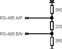
c)Termination Resistor In order to avoid reflexions, the line must be terminated with a resistor at both ends of the field bus. The transmission line can transmit the energy correctly only when a correct resistor is applied. The resistance of the terminator at every end of a network segment must match the wave resistance of the line, which is independant of the line length. If a type A according to EN50170-Profibus data transmission wire is used, the following combinations of resistances apply: |
Termination Resistor Wave Resistance |
||||||||||||||||||||||||
|
|
CAUTION!
This termination resistor ist not suited for e.g. line type B. For different line types, the
termination resistor must always be adjusted.
|